9. The infi RGB ring
9.1. The infi RGB Ring Module
The infi RGB ring may also plug into the adapter board.
Here we use the same wiring scheme as the ultrasonic module.
Adapter-Mainboard
- V —— 5V
- 1 —— D2
- G —— GND
- 2 —— D3
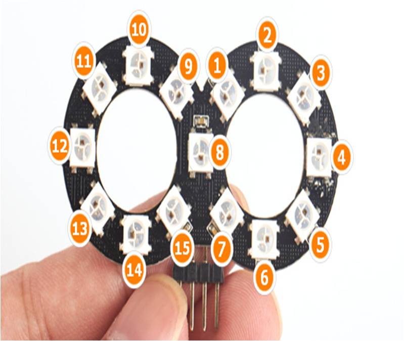
The pixel arrangement is shown in the pic below
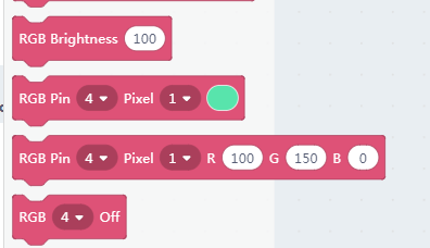
9.2. Blocks for RGB pixels
Here we have more than two pixels and more freedom of coding. The blocks for RGB are the same as chapter 5.
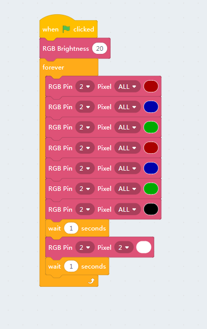
9.3. Testing the RGB module
We make a simple blinking testing programme to loop between RGB colors. Please note that a Black actually means turn the RGB off.
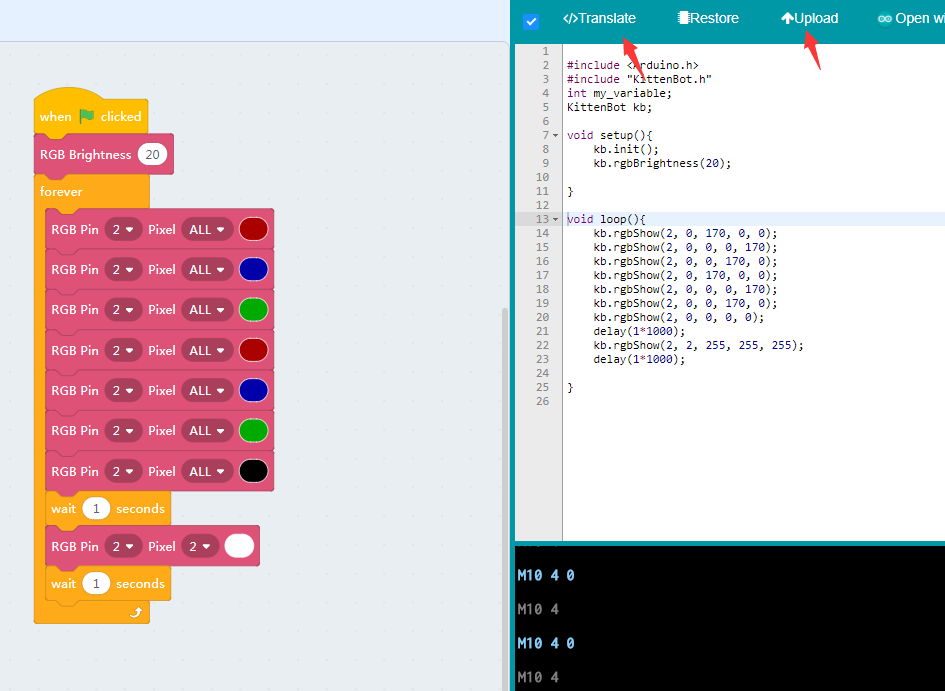
Make sure you have restored the firmware before using online mode
Then we translate it to arduino code and download.
9.4. The final effect
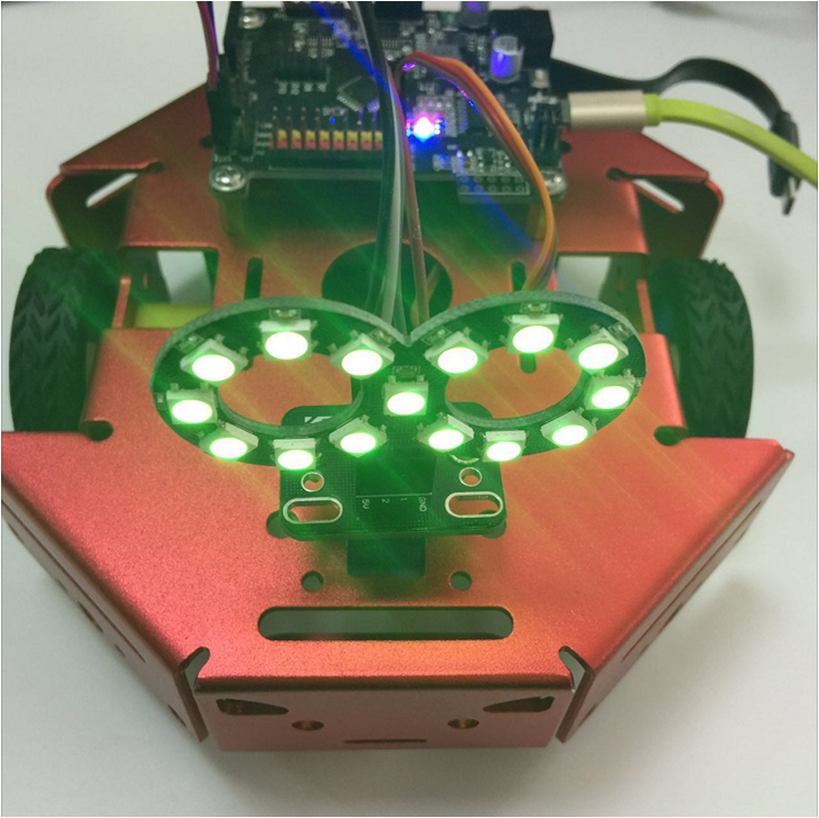
The chapter 7 to 9 could be kind of tedious but may get you familiar to kittenblock and the wiring process.