1. Microbit line following and avoidance robot kit
1.1. Product Purpose
This kit is designed for makers or training institutions as a system of obstacle avoidance and others courses, and suitable for ordinary enthusiasts and makers to expand projects. We a complete graphical coding software support for this kit.
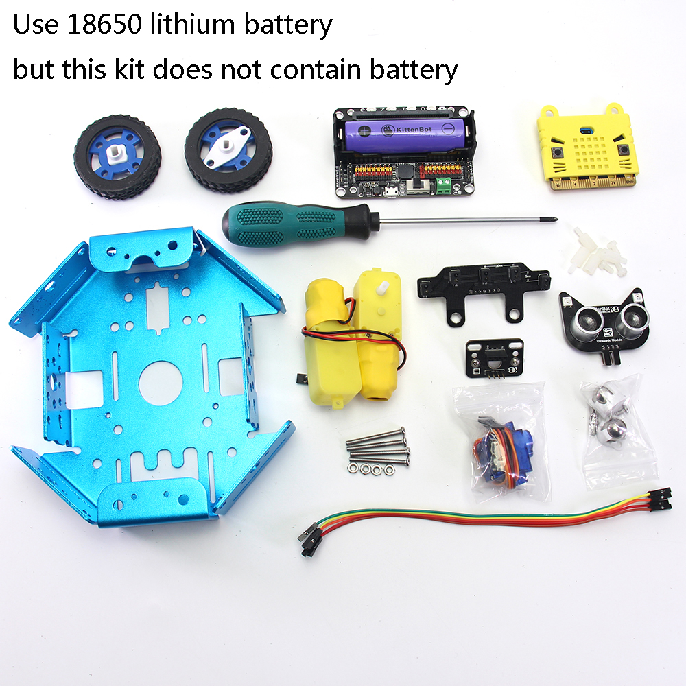
1.2. Product List
- Metal Chassis x1
- Microbit x1
- Robotbit x1
- TT Motor x2
- 9g servo parts package x1
- Five-channel line following module x1
- Nekomimi ultrasound module x1
- Adapter plate x1
- Board support stub and screw x4
- M3 screw several
- M4 screw/nut x2
- Wheel caster x2
- Dupont wire several
- Screwdriver x1 (Does not contain battery)
1.3. Product introduction
This is a robotic product that combines obstacle avoidance and line following functions. For most people, they only hear or contact these applications through the electronic competition in college, but such assemble and programming process is complex and redundant, which basically sets a technology barrier for non-technique majors. Whether by choosing hardware component or writing code has sumped people who have an interest or idea on such projects. However, Micorbit combined with its expansion board Robotbit affiliate with graphical programming software support, there is no hard or hash work on fixing errors from library loading, nor the assembly of the kit, which greatly reduces the technical barrier. This makes people without a master degree on tech can also quickly get started and play their own intelligent robots based on their interests.
1.4. Product Parameters
- Dimensions: 170mm x 145mm x 110mm
- Net weight (without packaging): 390g
1.5. Specification
- 18650 battery voltage: 3.7V
- Operating voltage:5V
- Output current:1A(Supported by onboard battery)
1.6. Assembly step
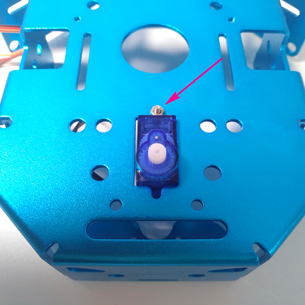
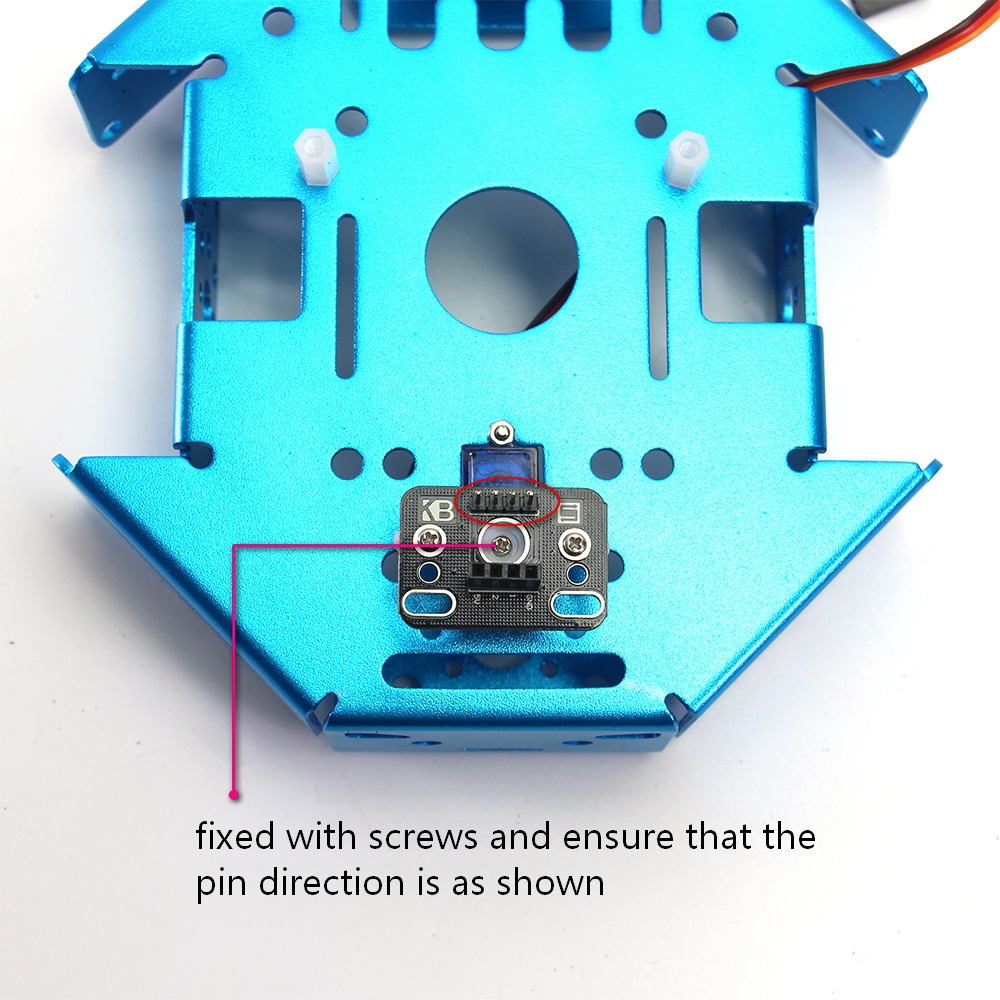
Insert 9g from the back to the chassis and secure it with the screws and nuts in the servo parts package.
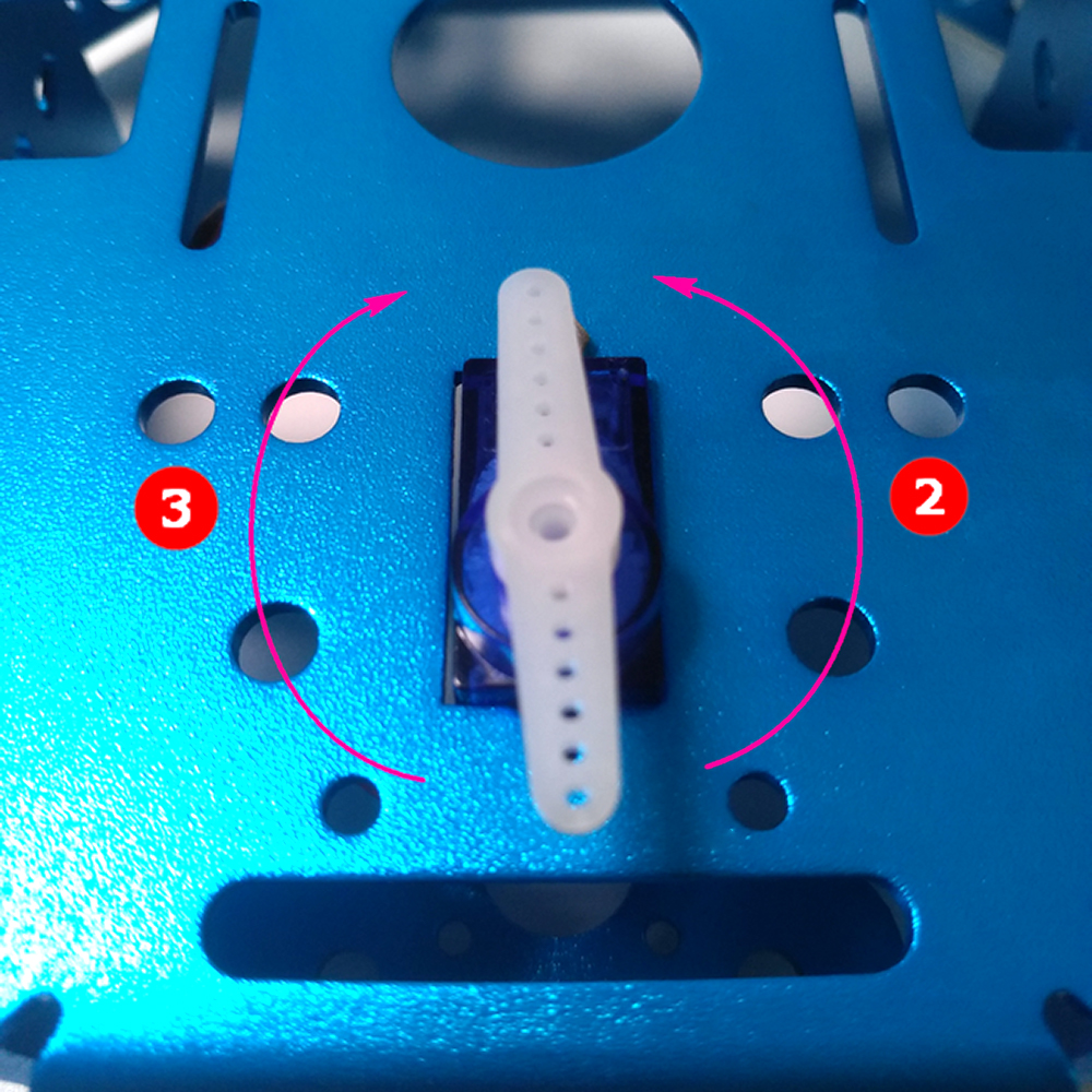
Mount the bracket onto the servo rotor and check whether the left and right rotation limit angles. Basically, you should give same rotate freedom to both clockwise and anticlockwise.
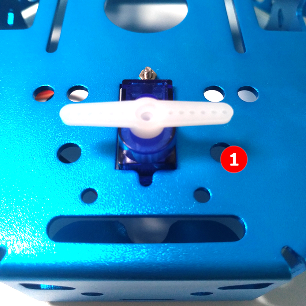
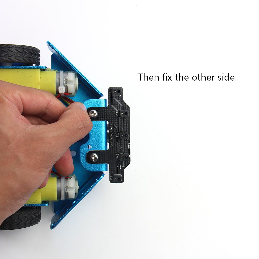
Let the servo geer keep in its middle position. Install the bracket to the adapter plate with screws.
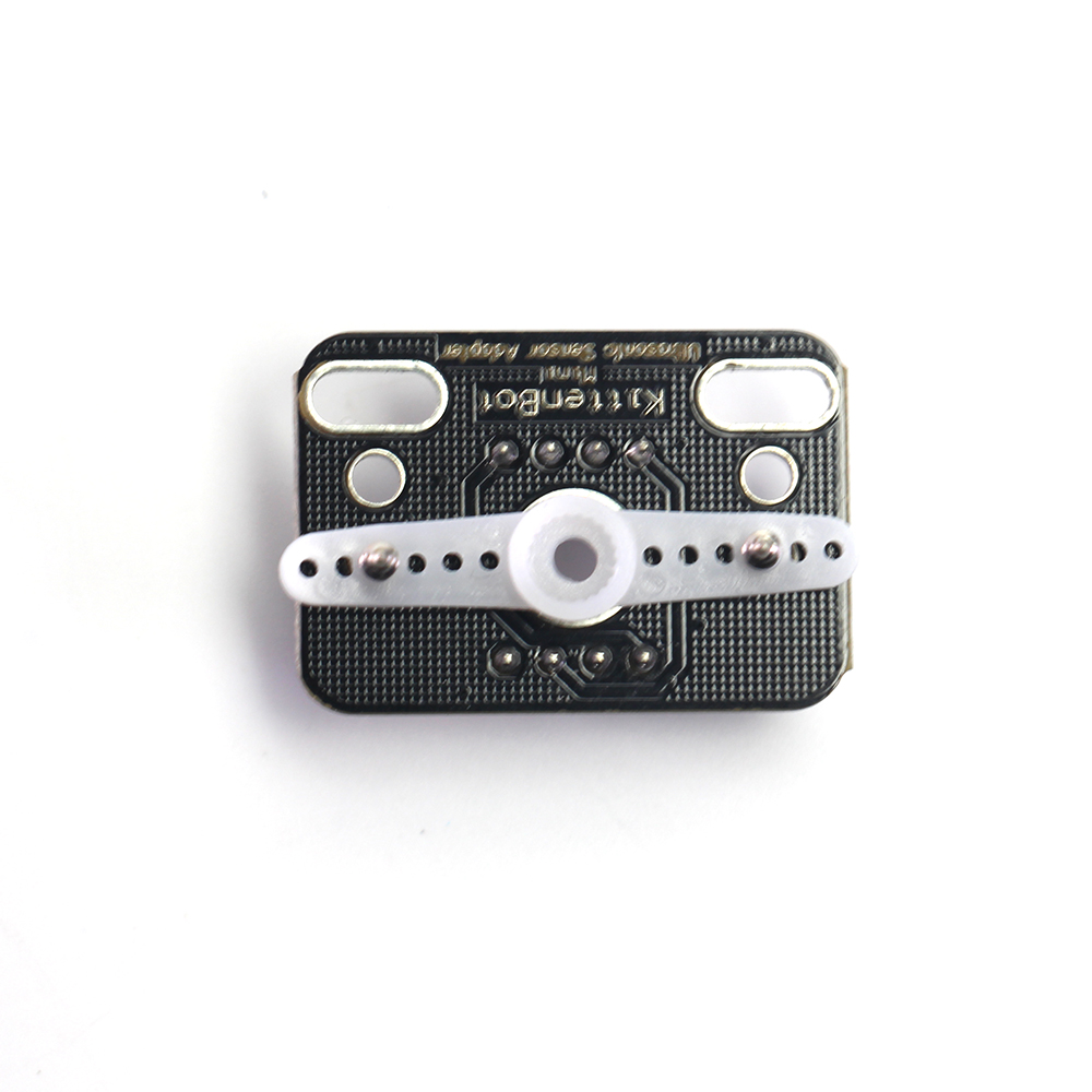
Insert the assembled parts on the servo rotor and tighten it with the small screws from the servo part package.
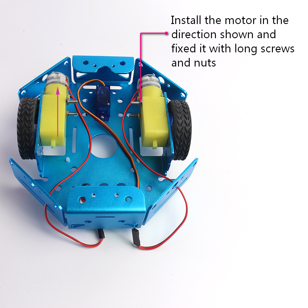
The TT motor screwed from the outside and the nut is fixed inside.
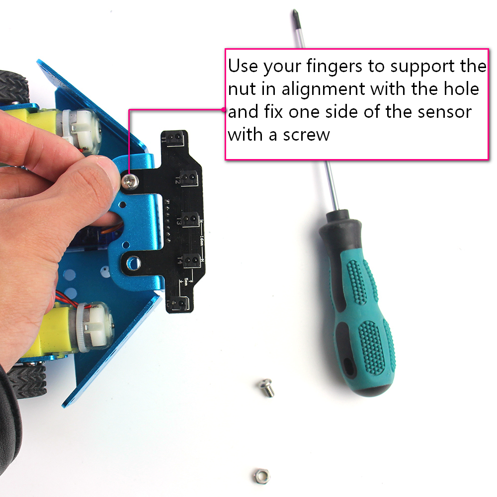
Tips on Installing the five-way line following module
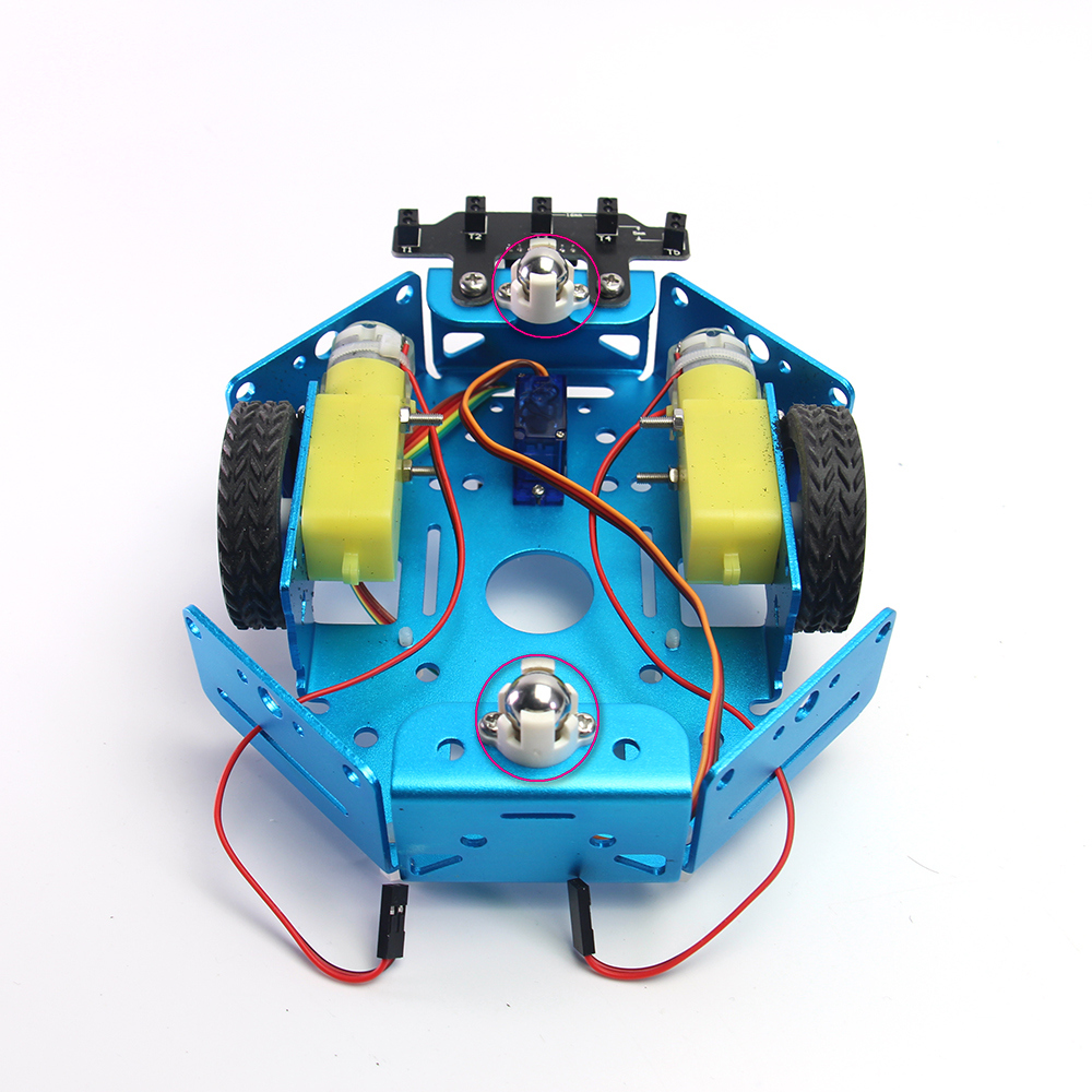
Two wheel caster installed on the front and back pallet.
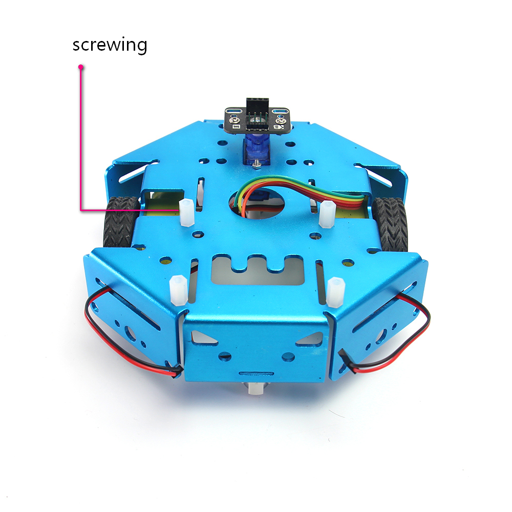
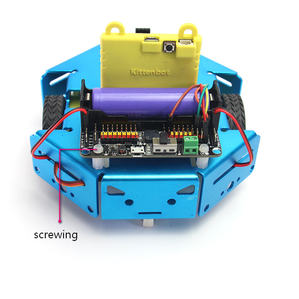
Plastic stub support for the robotbit. The mount hole is already threaded.
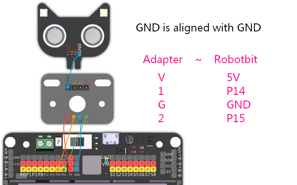
Wiring the ultrasonic sensor
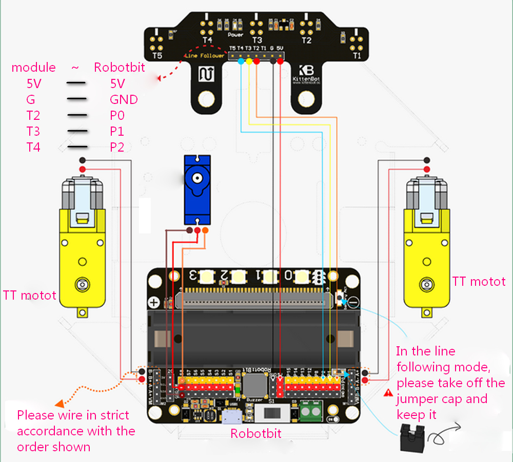
Wiring the five-channel line following sensor
Finished product display
1.7. Programming part
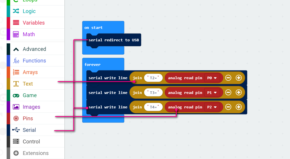
First we have to calibrate the infra sensor by reading the raw value of each sensor responding to black line.
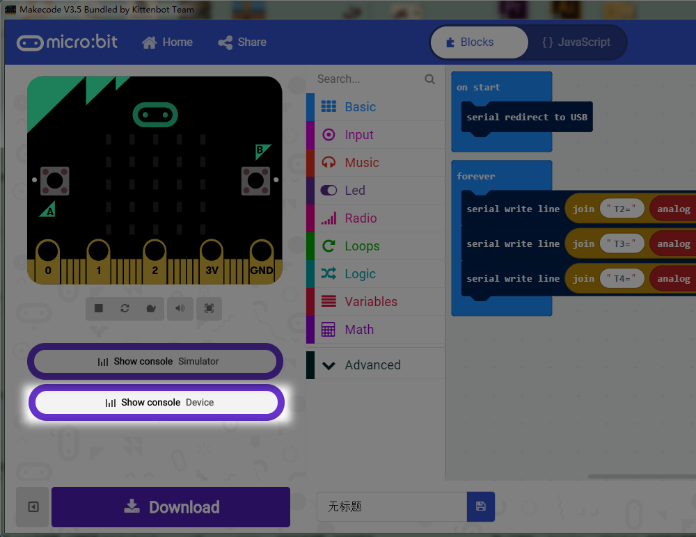
First download the following serial port test program to micro:bit
https://makecode.microbit.org/_Cz94f2RrqTYf
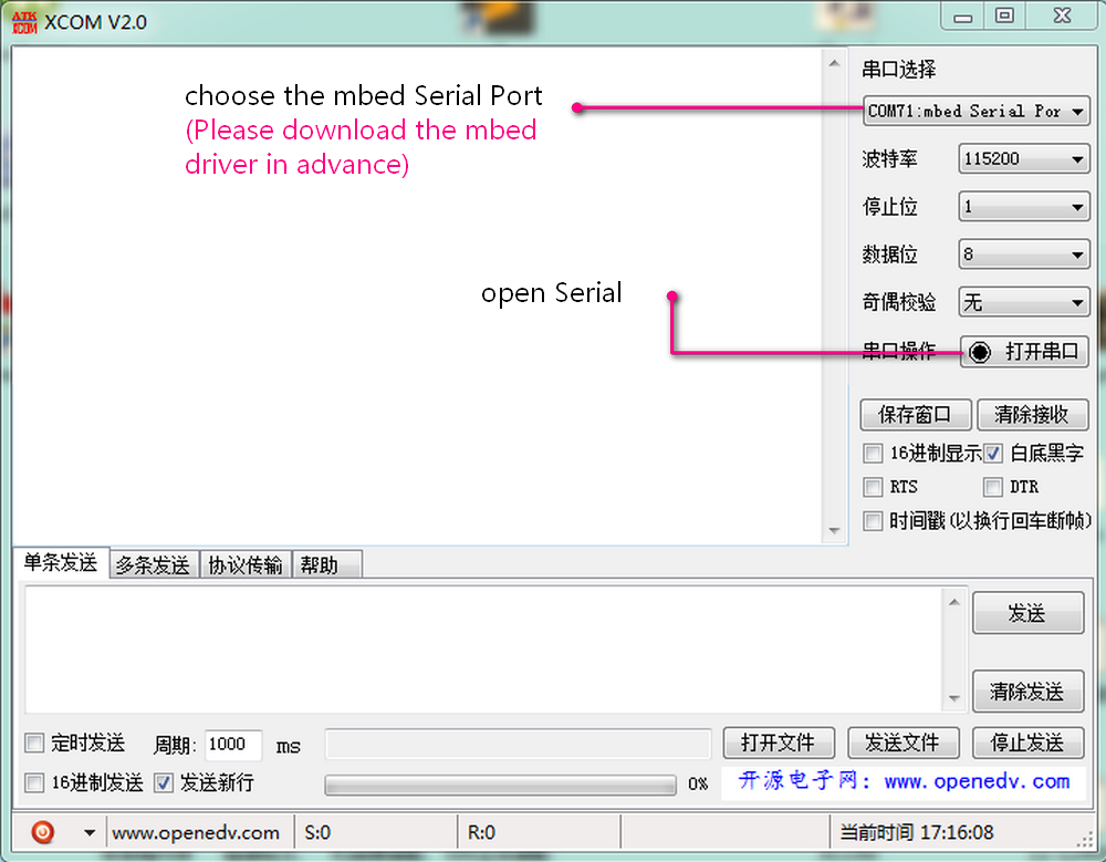
Then use the makecode or serial monitor tool to observe the output. The makecode offline version has inherit device console monitor, or you can use any serial monitor tool handy to you (even a arduino IDE).
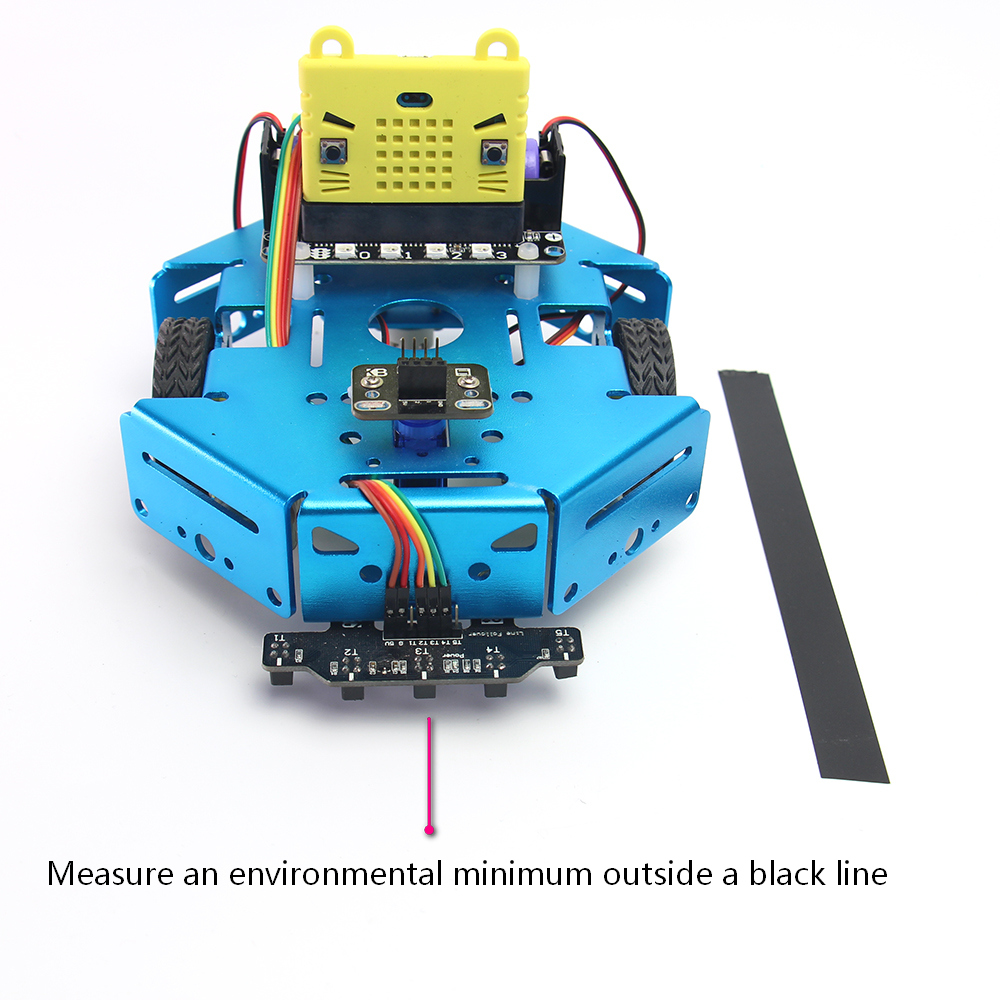
 First, measure the normal value when out of black tape.
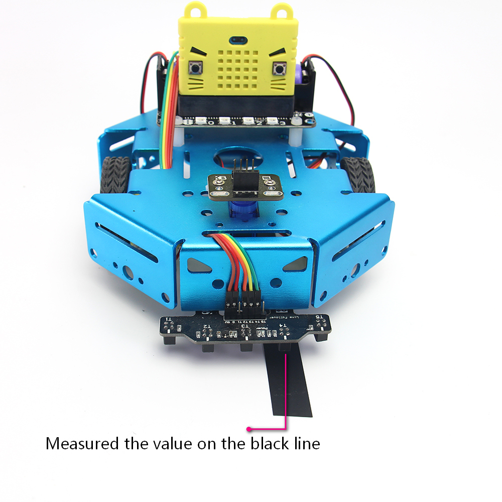
Second, measure the value when sensor over a black tape. Mark down all these online or outline value for each sensor, we need them in the next steps.
Three-channel line following
- working principle
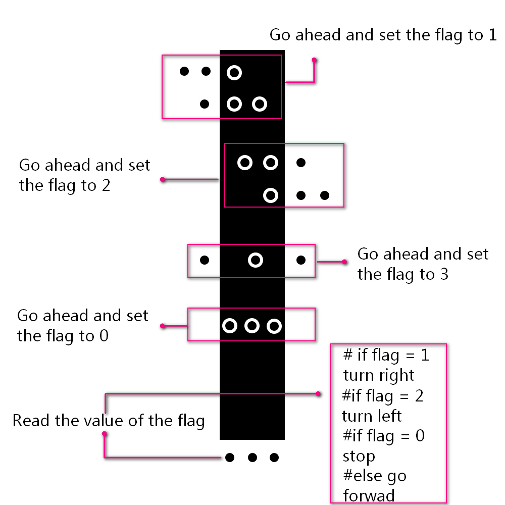
- program
https://makecode.microbit.org/_byh2fWUrF3u2
Ultrasonic obstacle avoidance
- working principle
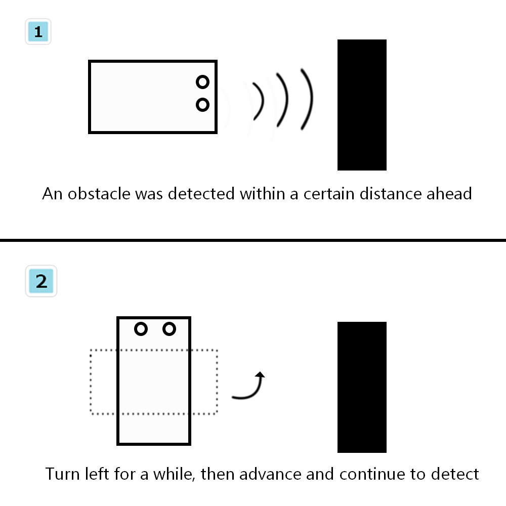
- program
1.9. Attentions
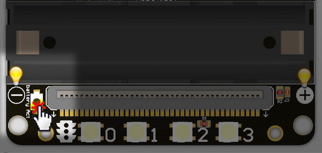
- Each time you plug in the battery and turn on the switch. The first thing you need to do is to activate the power supply.
- Regarding the wiring rule of the TT motor, the red wire indicate the positive sign and the black wire the negative sign. In this way, the positive number in the program can control the motor to rotate clockwise.
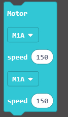
If you found the motor rotate contrary to expectations, just inverse the wiring terminal.
- The P0 pin is required when using the line following function,since the P0 pin is multiplexed with the buzzer, it is necessary to take out the jumper cap and keep it in a safe place.
This product is only suitable for children over the age of 14 for independent use. Children aged 8-14 should be accompanied by parents or teachers. Please use the instructions according to the official information before use. Do not plug in the circuit casually. Do not connect a large current servo or a high current motor to avoid burning the circuit board. Be careful not to place the control board on a metal surface or on a conductive object to avoid a short circuit. Avoid using it in wet and watery places to avoid short circuits. Do not swallow any small objects on the circuit board or machinery. Keep them out of the reach of children.